Revista Colombiana de
Tecnologías de Avanzada
Tecnologías de Avanzada
Recibido: 14 de marzo de 2022
Aceptado: 26 de septiembre de 2022
Aceptado: 26 de septiembre de 2022
MECHATRONIC DESIGN OF A COMPLIANT KNEE ORTHOSIS FOR REHABILITATION
DISEÑO MECATRÓNICO DE UNA ÓRTESIS FLEXIBLE DE RODILLA PARA REHABILITACIÓN
MSc. David Torres*, Ing. Chaves Ricardo*, Ing. Cortes Sergio*, PhD. Arcos-Legada Jaime*
* Universidad de San Buenaventura, School of Engineering, Mechatronics Engineering.
Cra 8H 172 - 20, Bogotá, Cundinamarca, Colombia.
+57 601 6701090.
E-mail: {dtorres, warcos}@usbbog.edu.co
Cómo citar: Torres, D., Chaves, R., Cortes, S., & Arcos Legada, J. (2022). DISEÑO MECATRÓNICO DE UNA ÓRTESIS FLEXIBLE DE
RODILLA PARA REHABILITACIÓN. REVISTA COLOMBIANA DE TECNOLOGIAS DE AVANZADA (RCTA), 2(40), 134-141.
https://doi.org/10.24054/rcta.v2i40.2361
Derechos de autor 2022 Revista Colombiana de Tecnologías de Avanzada (RCTA).
Esta obra está bajo una licencia internacional Creative Commons Atribución-NoComercial 4.0.

Esta obra está bajo una licencia internacional Creative Commons Atribución-NoComercial 4.0.

Resumen: Este trabajo presenta el diseño mecatrónico de un prototipo de órtesis de rodilla para la rehabilitación de la
marcha. El prototipo desarrollado utiliza un actuador en serie elástico, el cual es diseñado y evaluado con análisis de elementos finitos. El
actuador elástico en serie está acoplado a un motorreductor DC que proporciona el par necesario para automatizar una terapia post-quirúrgica
de rodilla. La órtesis está equipada con dos encoders incrementales y un interruptor de inicio para supervisar y controlar el movimiento de la
articulación de la rodilla. Se desarrolla y valida experimentalmente un modelo matemático no lineal de la órtesis. Esto permite desarrollar un
control basado en modelos, con una estrategia de control en espacio de estados por retroalimentación y un observador de estados. Finalmente,
el prototipo se evalúa siguiendo una trayectoria periódica suave que reproduce las actividades terapéuticas.
Palabras clave: órtesis de rodilla, diseño mecatrónico, articulación flexible, junta adaptable, actuador elástico serial.
Abstract: This paper presents a mechatronic design of a compliant knee orthosis prototype for a gait rehabilitation. The prototype developed implements an elastic serial actuator (SEA), which is evaluated using finite element analysis method. An elastic serial actuator is coupled to a DC gearmotor that supplies the necessary torque to automate a post-surgical knee recovery therapy process. The orthosis includes two incremental encoders and a switch, which are used to develop a feedback control of the knee joint movement. In addition, a nonlinear mathematical model of the orthosis is developed and experimentally validated. Hence, a model-based control is implemented with a state feedback control strategy. Finally, the prototype is evaluated through the tracking of a smooth periodic trajectory that reproduce the movements of a therapy cycle.
Keywords: Knee orthesis, biomechatronics, mechatronic design, flexible joint, compliant joint, series elastic actuator.
Therefore, a solution to the knee rehabilitation and therapy processes is analyzed for the problems set forth above, a proposal established from the field of Mechatronics Engineering and Biomedical Engineering, in which the design of a functional robotic device that guarantee more precise and efficient therapeutic processes
The implementation of a robotic treatment is based on the complementary use of controlled devices to perform movement routines that allow personalization of rehabilitation therapies according to the needs of the patient and therefore a faster progress in their recovery can be obtained from an approach medical-technical. From the patients' perspective, these controlled treatments with the use of robotic systems decrease the time of hospitalization and postsurgical recovery. To support traditional therapy effectively, it is needed to achieve a natural movement that ensures patient safety; accordingly, the robots or rehabilitation machines need to meet some technical and medical requirements such as precise control of the applied torque, a movement synchronized with the frequency of the patient's muscle movement, as well as the driving of the knee movement characterized by a low mechanical impedance of the implemented mechanism
This paper proposes a SEA based on the mechanical design of the torsion spring, which in addition to allowing the transmission of movement, also attenuates the misalignment effect between the actuator's axis of rotation and the knee's axis of rotation.
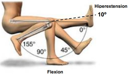
Finally, the range of motion for the extension of the lower limb is selected from 0◦ to 90◦, ensuring that the knee can only move at a safe angle, thereby avoiding hyperextension or unnatural movements of the leg (Fig. 1).
Regarding to the stiffness of the SEA for assistance in locomotion, a selection of this parameter is estimated within a range between 100 Nm / rad and 300 Nm / rad, the selection of a stiffness value of 170 Nm / rad is proposed, given that the treatment of knee injury rehabilitation is sitting position
Regarding the analysis with the FEM method, two fundamental criteria were evaluated, the Von Mises stresses and the unit deformations. The Von Mises stresses guarantee that the element does not exceed the elastic limit of the implemented material and the unit deformations ensure that the element will not undergo plastic deformation due to the torque provided by the actuator, a torque of 14 Nm according to the technical specifications of the selected motor.
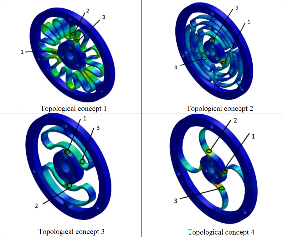
In this way, three critical points are studied for this project, denoted on a scale from 1 to 3, in which 1 being the maximum value and 3 the minimum value. The result of the FEA analysis is presented below for each of the 4 defined topologies of the project (Fig. 2).
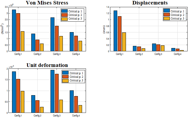
Then, the results of the previous studies are evaluated by analyzing the Von Mises stress criteria, displacements, and unit deformations (Fig.3) using a selection matrix, through a weighted comparative study of the different topologies previously exposed, in which the most suitable topology is chosen for the implementation of the knee orthosis design. Based on this, the comparative selection matrix is made (table I), in which the displacement is established as the most important criterion since it depends on the stiffness of the spring, followed by the mass with an intermediate evaluation and finally the tension of Von Mises and strains with a lower rating.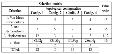
Finally, based on the results obtained in the selection matrix, concept 1 is defined as the topology with the highest rate value.
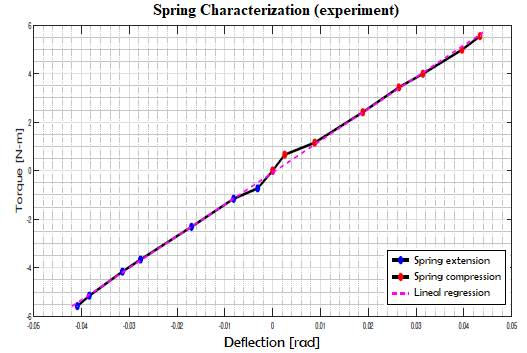
To validate the estimation of the constant, the elastic constant was experimentally found. In this case, the duty cycle of the PWM signal that drives the motor is modified, which produces a change in the motor's torque output. This change is used to guarantee a constant mechanical load. Additionally, using dial comparators, the deformation of the spring is measured and then a linear regression procedure carried out with the previous simulation data, the result of which can be seen in Fig. 4. The data of the elastic constant of the spring is presented in Table II.
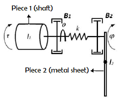
Considering the schematic representation shown above for the assembly of the SEA, the following mathematical model (Fig. 6) of the system is proposed by the Euler-Lagrange in equation (2).
\[ D(q) \ddot{q} + C(q, \dot{q}) \dot{q} + G(q) = \tau \hspace{1cm}(2)\] where \( q = \begin{bmatrix} \theta\phi \end{bmatrix}^\tau \), \( D = \begin{bmatrix} I_1 & 0 \\ 0 & m_2 l^2 \end{bmatrix} \), \( C = \begin{bmatrix} \beta_1 & 0 \\ 0 & \beta_2 \end{bmatrix} \), \( G = \begin{bmatrix} k(\phi - \theta) \\ k(\phi - \theta) + m_2 gl \sin(m_2) \end{bmatrix} \)
To define the controller and observer gains, a discrete model of the plant is given by a zero-order hold approximation as: \[ G_z = (1 - Z^{-1}) \cdot Z\left\{\frac{G_\lambda}{s}\right\} = (1 - Z^{-1}) \cdot Z\left\{\frac{12.49}{s^4 + 16.68s^3 + 210.4s^2 + 703.2s}\right\} \] \[ G_z = \frac{5.0318 \times 10^{-9} \cdot (z + 0.9568)(z + 0.9672)(z + 0.0977)}{(z + 0.9558)(z - 1)(z^2 - 1.871z + 0.8855)} \] This allows to define an augmented system that includes the controller and system dynamics. This augmented system is defined as: \[ x_a(k+1) = A_a x_a - B_a u(k) + F_a \text{ref}(k) \hspace{1cm}(10)\] The augmented representation allows to define the the closed-loop dynamics, which is given by: \[ x_a(k+1) = A_a x_a - B_a K_a x_a + F_a \text{ref} \hspace{1cm}(11)\] Finally, using a pole-placement algorithm, the controller gains are: \[k1=-4.1408,\hspace{0.5cm}k4=-38.9700,\] \[k2=-8.8853,\hspace{0.5cm}kc1=-0.2032,\] \[k3=-3.9288,\hspace{0.5cm}kc2=-0.2025\] A classical Luenberger state observer is designed to estimate the unmeasured system states. Following the separability principle, the observer poles are selected to be: \[z1o=-0.9868,\hspace{0.5cm}z4o=-0.9835,\] \[z2o=-0.9835,\hspace{0.5cm}z5o=-0.2032\] \[z3o=-0.9802,\] which are obtained through the selection of the observer gains as: \[z1o=0.5.5151,\hspace{0.5cm}z4o=0.1930,\] \[z2o=-18.7610,\hspace{0.5cm}z5o=58.7368\] \[z3o=17.5567,\]
As it can be seen, the implemented control system meets the requirements of the trajectory tracking implemented during the test.
L. Calderita, P. Bustos, C. S. Mejías, F. Fernández, R. Viciana, and A. Bandera, 2016. “Asistente robótico socialmente interactivo para terapias de rehabilitación motriz con pacientes de pediatría,” Revista Iberoamericana de Automática e Informática industrial, vol. 12, no. 1, pp. 99–110.
P. D. Neuhaus, J. H. Noorden, T. J. Craig, T. Torres, J. Kirschbaum, and J. E. Pratt, 2011. “Design and evaluation of mina: A robotic orthosis for paraplegics,” IEEE international conference on rehabilitation robotics. IEEE, 2011, pp. 1–8.
D. Ferris, G. Sawicki, and A. Domingo, “Powered lower limb orthoses for gait rehabilitation,” Topics in spinal cord injury rehabilitation, vol. 11, no. 2, pp. 34–49, 2005.
E. B. Castán, P. M. Ribas, M. V. Araiz, M. Aznar, R. V. Pascual, F. N. Teixido et al., 2012. “Dolor anterior de rodilla. una revisión en imágenes.” European Society of Radiology.
A. Espejo-Reina, M. Espejo Reina, G. García-Gutiérrez, J. Dalla Rosa Nogales, A. P. de la Blanca-Cobos, M. Prado, and A. E. Baena, 2018. “Lesiones de las raíces meniscales. estado actual,” Rev Esp Artrosc Cir Articul, vol. 25, no. Supl 1, pp. 29–45.
J. Raya Gonzalez, P. Gomez Piqueras, and J. Sanchez Sánchez, 2018. “Effect of an eccentric load resistance training program on the rehabilitation of medial collateral ligament injuries. a case study”, Retos nuevas tendencias en educación física deporte y recreación, no. 33, pp. 157—161.
W. M. Dos Santos, G. A. Caurin, and A. A. Siqueira, 2017. “Design and control of an active knee orthosis driven by a rotary series elastic actuator,” Control Engineering Practice, vol. 58, pp. 307–318.
N. Paine, S. Oh, and L. Sentis, 2013. “Design and control considerations for high-performance series elastic actuators,” IEEE/ASME Transactions on Mechatronics, vol. 19, no. 3, pp. 1080–1091.
W. J. Arcos-Legarda, 2013. “Control automático de un exoesqueleto de marcha para pacientes con discapacidad motora,” Tesis maestría, Universidad Nacional De Colombia.
C. Ortiz, F. Fernando et al., 2010. “Estudio de la resistencia de fatiga del acero sae 5160 antes y después de proceso shot peening,” B.S. thesis, Universidad Autónoma de Occidente.
S. Hernández, “Anatomía de la pierna humana,” catarina UDLAP.
F. Sergi, D. Accoto, G. Carpino, N. L. Tagliamonte, and E. Guglielmelli, 2012. “Design and characterization of a compact rotary series elastic actuator for knee assistance during overground walking,” 4th IEEE RAS & EMBS International Conference on Biomedical Robotics and Biomechatronics (BioRob). IEEE, 2012, pp. 1931– 1936.
Palabras clave: órtesis de rodilla, diseño mecatrónico, articulación flexible, junta adaptable, actuador elástico serial.
Abstract: This paper presents a mechatronic design of a compliant knee orthosis prototype for a gait rehabilitation. The prototype developed implements an elastic serial actuator (SEA), which is evaluated using finite element analysis method. An elastic serial actuator is coupled to a DC gearmotor that supplies the necessary torque to automate a post-surgical knee recovery therapy process. The orthosis includes two incremental encoders and a switch, which are used to develop a feedback control of the knee joint movement. In addition, a nonlinear mathematical model of the orthosis is developed and experimentally validated. Hence, a model-based control is implemented with a state feedback control strategy. Finally, the prototype is evaluated through the tracking of a smooth periodic trajectory that reproduce the movements of a therapy cycle.
Keywords: Knee orthesis, biomechatronics, mechatronic design, flexible joint, compliant joint, series elastic actuator.
1. INTRODUCTION
Traumatic or inflammatory conditions of the knee are the main causes of consultation in clinics in cases of gait rehabilitation
[1]
. The care of these injuries in the lower extremities requires prolonged treatments with therapy sessions to activate and strengthen the
muscles responsible for the normal movement of the knee. These treatments result in intensive and exhausting sessions both for the medical
personnel in charge of performing the therapies and for the patients themselves. Situation that leads to different problems due to the rigor
and repeatability that must be achieved in the different therapy sessions
J. Vergara, M. Díaz, A. Ortega, J. Blanco, J. Hernández, and Herrera, 2004. “Protocolo de valoración de la patología de la rodilla,”
Semergen, vol. 30, no. 5, pp. 178–87.
[2]
.
L. Calderita, P. Bustos, C. S. Mejías, F. Fernández, R. Viciana, and A. Bandera, 2016. “Asistente robótico socialmente interactivo para
terapias de rehabilitación motriz con pacientes de pediatría,” Revista Iberoamericana de Automática e Informática industrial, vol. 12, no.
1, pp. 99–110.
Therefore, a solution to the knee rehabilitation and therapy processes is analyzed for the problems set forth above, a proposal established from the field of Mechatronics Engineering and Biomedical Engineering, in which the design of a functional robotic device that guarantee more precise and efficient therapeutic processes
[3]
. In recent years, a new line of research focused on Rehabilitation Engineering has proposed novel technologies as alternatives to traditional
treatments. An example of this are the electro-functional exercises that stimulate the motor cortex and promote the recovery of mobility
P. D. Neuhaus, J. H. Noorden, T. J. Craig, T. Torres, J. Kirschbaum, and J. E. Pratt, 2011. “Design and evaluation of mina: A robotic
orthosis for paraplegics,” IEEE international conference on rehabilitation robotics. IEEE, 2011, pp. 1–8.
[4]
. About knee rehabilitation, isometric exercises are used as rehabilitation methods, which correspond to the extension of the quadriceps and
the other are isotonic exercises that correspond to the use of weights and elastic resistance elements to activate and strengthen the muscles
after a traumatic event. These exercises are constantly used for the treatment of the four most common pathologies that physiotherapists
treat: simple contusion
D. Ferris, G. Sawicki, and A. Domingo, “Powered lower limb orthoses for gait rehabilitation,” Topics in spinal cord injury rehabilitation,
vol. 11, no. 2, pp. 34–49, 2005.
[5]
, ligament and meniscus injury
E. B. Castán, P. M. Ribas, M. V. Araiz, M. Aznar, R. V. Pascual, F. N. Teixido et al., 2012. “Dolor anterior de rodilla. una revisión en
imágenes.” European Society of Radiology.
[6]
, internal or external lateral ligament tear, and cruciate ligament tear
A. Espejo-Reina, M. Espejo Reina, G. García-Gutiérrez, J. Dalla Rosa Nogales, A. P. de la Blanca-Cobos, M. Prado, and A. E. Baena, 2018.
“Lesiones de las raíces meniscales. estado actual,” Rev Esp Artrosc Cir Articul, vol. 25, no. Supl 1, pp. 29–45.
[7]
.
J. Raya Gonzalez, P. Gomez Piqueras, and J. Sanchez Sánchez, 2018. “Effect of an eccentric load resistance training program on the
rehabilitation of medial collateral ligament injuries. a case study”, Retos nuevas tendencias en educación física deporte y recreación,
no. 33, pp. 157—161.
The implementation of a robotic treatment is based on the complementary use of controlled devices to perform movement routines that allow personalization of rehabilitation therapies according to the needs of the patient and therefore a faster progress in their recovery can be obtained from an approach medical-technical. From the patients' perspective, these controlled treatments with the use of robotic systems decrease the time of hospitalization and postsurgical recovery. To support traditional therapy effectively, it is needed to achieve a natural movement that ensures patient safety; accordingly, the robots or rehabilitation machines need to meet some technical and medical requirements such as precise control of the applied torque, a movement synchronized with the frequency of the patient's muscle movement, as well as the driving of the knee movement characterized by a low mechanical impedance of the implemented mechanism
[8]
.
W. M. Dos Santos, G. A. Caurin, and A. A. Siqueira, 2017. “Design and control of an active knee orthosis driven by a rotary series elastic
actuator,” Control Engineering Practice, vol. 58, pp. 307–318.
2. SEA ACTUATOR DESIGN
Serial elastic actuators (SEA) are alternative elements to the traditional motion transmission systems with rigid mechanisms. This type of actuators contains an elastic element in series with the mechanical energy source. Among the main advantages of these elements is that it allows to achieve a low mechanical output impedance, has a tolerance to impact loads, increases the maximum output power and can establish a passive storage of mechanical energy. These properties align with robustness, high power output, and energy efficient requirements in physical therapy automation systems
[9]
.
N. Paine, S. Oh, and L. Sentis, 2013. “Design and control considerations for high-performance series elastic actuators,” IEEE/ASME
Transactions on Mechatronics, vol. 19, no. 3, pp. 1080–1091.
This paper proposes a SEA based on the mechanical design of the torsion spring, which in addition to allowing the transmission of movement, also attenuates the misalignment effect between the actuator's axis of rotation and the knee's axis of rotation.
2.1 Design Parameters
To establish the design parameters of the SEA, a study of the torque necessary to achieve the movement of the weight of the lower limb was carried out. This process takes into consideration anthropometric data from the lower limb of a 50th percentile from different people
[10]
. Next, with these data, the torque necessary to achieve the movement of the lower limb is calculated with equation (1). Assuming that the
lower limb is suspended and that the patient does not perform any type of voluntary movement that generates external forces in the device
attached to the lower limb. \[ T = \sin(\theta) \cdot d \hspace{1cm} (1)\]\[ T = 4.559 \, \text{Nm} \] Considering the torque required for the
device and the desired mechanical properties, SAE 5160 steel is selected for the manufacture of the spring, an alloy material with chromium of
high hardness and medium hardenability, ideal for the manufacture of coil springs. After a heat treatment process (quenched at 850 degrees
Celsius), this material has an approximate elastic limit of 1020 MPa and a Young's modulus of 203.68 GPa
W. J. Arcos-Legarda, 2013. “Control automático de un exoesqueleto de marcha para pacientes con discapacidad motora,” Tesis maestría,
Universidad Nacional De Colombia.
[11]
. On the other hand, the chosen motor is a 76 RPM Spur Gear motor, which has a 107: 1 gearbox, an encoder with 7 cycles per revolution hall
effect magnetic sensors and a nominal output torque of approximately 14 Nm.
C. Ortiz, F. Fernando et al., 2010. “Estudio de la resistencia de fatiga del acero sae 5160 antes y después de proceso shot peening,” B.S.
thesis, Universidad Autónoma de Occidente.
Finally, the range of motion for the extension of the lower limb is selected from 0◦ to 90◦, ensuring that the knee can only move at a safe angle, thereby avoiding hyperextension or unnatural movements of the leg (Fig. 1).

Fig. 1. Sagittal plane of the knee joint.
[12]
S. Hernández, “Anatomía de la pierna humana,” catarina UDLAP.
2.2 Analysis and results of configurations by means of finite element analysis (FEM)
According to the parameters defined above, 4 possible topologies are established for the design of the SEA that adapt to the design requirements (figure 2). Then, a finite element analysis (FEA) is carried out, in which the dimensional parameters of the elastic component of the SEA are established as: external diameter of 100 mm, internal diameter of 85 mm and diameter of the central element of 28mm [13,8].Regarding to the stiffness of the SEA for assistance in locomotion, a selection of this parameter is estimated within a range between 100 Nm / rad and 300 Nm / rad, the selection of a stiffness value of 170 Nm / rad is proposed, given that the treatment of knee injury rehabilitation is sitting position
[13]
. Similarly, the thickness of the elastic element of the SEA is estimated in a range of 6mm and 8mm
F. Sergi, D. Accoto, G. Carpino, N. L. Tagliamonte, and E. Guglielmelli, 2012. “Design and characterization of a compact rotary series
elastic actuator for knee assistance during overground walking,” 4th IEEE RAS & EMBS International Conference on Biomedical Robotics and
Biomechatronics (BioRob). IEEE, 2012, pp. 1931– 1936.
[8]
. After performing the FEA analysis including the properties in the proposed models, a thickness of 6mm is defined to obtain the required
stiffness.
W. M. Dos Santos, G. A. Caurin, and A. A. Siqueira, 2017. “Design and control of an active knee orthosis driven by a rotary series elastic
actuator,” Control Engineering Practice, vol. 58, pp. 307–318.
Regarding the analysis with the FEM method, two fundamental criteria were evaluated, the Von Mises stresses and the unit deformations. The Von Mises stresses guarantee that the element does not exceed the elastic limit of the implemented material and the unit deformations ensure that the element will not undergo plastic deformation due to the torque provided by the actuator, a torque of 14 Nm according to the technical specifications of the selected motor.
In this way, three critical points are studied for this project, denoted on a scale from 1 to 3, in which 1 being the maximum value and 3 the minimum value. The result of the FEA analysis is presented below for each of the 4 defined topologies of the project (Fig. 2).

Fig. 2. CAD topological configurations.
Then, the results of the previous studies are evaluated by analyzing the Von Mises stress criteria, displacements, and unit deformations (Fig.3) using a selection matrix, through a weighted comparative study of the different topologies previously exposed, in which the most suitable topology is chosen for the implementation of the knee orthosis design. Based on this, the comparative selection matrix is made (table I), in which the displacement is established as the most important criterion since it depends on the stiffness of the spring, followed by the mass with an intermediate evaluation and finally the tension of Von Mises and strains with a lower rating.
Table 1: Selection Matrix


Fig. 3. Displacement, stress and strain analysis of the main topologies
Finally, based on the results obtained in the selection matrix, concept 1 is defined as the topology with the highest rate value.
2.3 Spring characterization
To identify the spring constant of the torsion spring for the selected topology, the FEA tools of the Solid-Edge software are used. In this process, the deformation of the spring under different static load values is measured. Next, a linear regression process is carried out that allows defining an estimate of the elastic constant of the spring at 166.1145 Nm / rad, a value close to the constant defined in the design requirements of 170 Nm / rad, with only an error of less 2.3%.
Fig. 4. Experimental results of the elastic constant
To validate the estimation of the constant, the elastic constant was experimentally found. In this case, the duty cycle of the PWM signal that drives the motor is modified, which produces a change in the motor's torque output. This change is used to guarantee a constant mechanical load. Additionally, using dial comparators, the deformation of the spring is measured and then a linear regression procedure carried out with the previous simulation data, the result of which can be seen in Fig. 4. The data of the elastic constant of the spring is presented in Table II.
Table 2: Elastic constant of torsion spring

3. MATHEMATICAL MODEL – EULER LAGRANGE
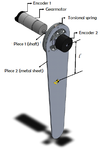
The mathematical model of the knee orthosis with the SEA is obtained considering that the gearmotor moves the lower limb through a torsion spring in series with the motor shaft. In addition, a metal sheet for the patient's lower limb support is included with the device and two encoders to measure motor angle and spring deflection angle. The schematic of the SEA model is presented in Fig. 5.
Fig. 5. Model schematic for the SEA
Considering the schematic representation shown above for the assembly of the SEA, the following mathematical model (Fig. 6) of the system is proposed by the Euler-Lagrange in equation (2).

Fig. 6. Mathematical model schematic
\[ D(q) \ddot{q} + C(q, \dot{q}) \dot{q} + G(q) = \tau \hspace{1cm}(2)\] where \( q = \begin{bmatrix} \theta\phi \end{bmatrix}^\tau \), \( D = \begin{bmatrix} I_1 & 0 \\ 0 & m_2 l^2 \end{bmatrix} \), \( C = \begin{bmatrix} \beta_1 & 0 \\ 0 & \beta_2 \end{bmatrix} \), \( G = \begin{bmatrix} k(\phi - \theta) \\ k(\phi - \theta) + m_2 gl \sin(m_2) \end{bmatrix} \)
4. CONSTRUCTION AND VALIDATION
The construction of the prototype is divided into three fundamental sections: the manufacture of the elastic actuator in series, the construction of a therapy bench where the physiotherapist can perform the therapies and the validation of the properties of the SEA actuator.4.1 Serial elastic actuator manufacturing.
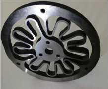
To manufacture the serial elastic actuator, it is carry out a tempering heat treatment to modify the physical properties of the material, which gave it a hardness of 40 on the Rockwell HRc scale. Regarding machining, first a pro-abrasion grinding process is carried out, followed by an EDM cutting process with wire that guarantees the precision and correct shape of the internal figure of the spring (Fig. 7).
Fig. 7. Torsional spring
4.2 Construction of a therapy testbed
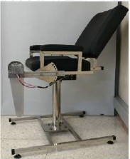
Considering that one of the primary requirements of the project is to prioritize the patient's posture with the axis of rotation of the mechatronic orthosis, the lower limb support is attached to the torsional spring, to avoid prolonged positions and allow the possibility of performing therapy at different angles, as is suggested by a physical therapist. This therapy testbed is built using 304 stainless-steel, with its respective graduation of the backrest and the attached prototype (Fig. 8).
Fig. 8. Therapy testbed
4.3 Validation of the model
For the validation of the model, it was proposed to implement a cross-validation technique, in which it can be verified if the proposed model can reproduce the output data for inputs that are not within the initial estimation, as shown in the following experiments. In this way, carrying out the validation of the system with these two experiments, a linear approximation of the nonlinear model is proposed that adjusts to the dynamics of the system around an operation point, represented by the following transfer function: \[ G(s) = \frac{12.49}{s^4 + 16.68s^3 + 210.4s^2 + 703.2s} \hspace{1cm}(3)\]5. CONTROLLER DESIGN IN STATE SPACE WITH OBSERVER
5.1 Controller design parameters
A model-based controller is implemented to track a reference signal with a ramp shape. Additionally, an overshoot (Mp) with a range less than or equal to 2%, for which a damping coefficient ζ = 0.8 is selected that ensures approximately a Mp = 1.52%, expressed in equation (4). Likewise, a stabilization time (ts) is chosen, a parameter that allows finding the natural frequency, defined in equation (5) as ts=3s, which meets the tolerance criterion of 2%. This frequency is useful to find the poles that meet the established conditions of the system. \[ M_p = e^{\frac{-\pi \zeta}{\sqrt{1 - \zeta^2}}} \hspace{1cm}(4)\] \[ t_s = \frac{4}{\zeta \omega_n} \hspace{1cm}(5)\] To meet the requirements of ts and Mp, the poles are defined as: \[ s = -\zeta \omega_n + \omega_d j \hspace{1cm}(6)\] To implement the controller into a microcontroller, a sampling period is selected based on the fastest pole, which is s=-25. Given the following equation: \[ t_s = 4\tau \hspace{1cm}(7)\] the stabilization time of the plant is approximately 0.16s, which allows to defined a sampling period of T=0.01s. Then, the poles in discrete time are: \[ z = e^{sT} \hspace{1cm}(8)\] \[ z_1 = 0.9867 + 0.0099j \] \[ z_2 = 0.9867 - 0.0099j \] Since the plant has four states, the controller has two states, four more poles are added to the desired dynamics, which are listed below: \[ z_3 = e^{-6 \cdot 0.01} = 0.9418 \] \[ z_4 = e^{-13 \cdot 0.01} = 0.8781 \] \[ z_5 = e^{-20 \cdot 0.01} = 0.8187 \] \[ z_6 = e^{-25 \cdot 0.01} = 0.7788 \]
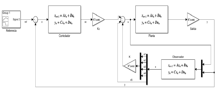
Fig. 9. Control Block Diagram
5.2 State space controller proposal
The controller’s dynamics is defined with a state feedback control law, which is assisted by a state observer that is shown in the Fig. 9. The control law is defined as: \[ u = -\begin{bmatrix} k & k_i \end{bmatrix} \begin{bmatrix} \hat{x} \\ x_c \end{bmatrix} \] \[ \dot{x_c} = A_c x_c + B_c e \] \[ \dot{\hat{x}} = (A - LC) \hat{x} + Bu + Ly \] where: \( A_c = \begin{bmatrix} 0 & 1 \\ -1 & 2 \end{bmatrix} \), \( B_c = \begin{bmatrix} 0 \\ 1 \end{bmatrix} \) and \( C_c = \begin{bmatrix} 1 & 0 \end{bmatrix} \)To define the controller and observer gains, a discrete model of the plant is given by a zero-order hold approximation as: \[ G_z = (1 - Z^{-1}) \cdot Z\left\{\frac{G_\lambda}{s}\right\} = (1 - Z^{-1}) \cdot Z\left\{\frac{12.49}{s^4 + 16.68s^3 + 210.4s^2 + 703.2s}\right\} \] \[ G_z = \frac{5.0318 \times 10^{-9} \cdot (z + 0.9568)(z + 0.9672)(z + 0.0977)}{(z + 0.9558)(z - 1)(z^2 - 1.871z + 0.8855)} \] This allows to define an augmented system that includes the controller and system dynamics. This augmented system is defined as: \[ x_a(k+1) = A_a x_a - B_a u(k) + F_a \text{ref}(k) \hspace{1cm}(10)\] The augmented representation allows to define the the closed-loop dynamics, which is given by: \[ x_a(k+1) = A_a x_a - B_a K_a x_a + F_a \text{ref} \hspace{1cm}(11)\] Finally, using a pole-placement algorithm, the controller gains are: \[k1=-4.1408,\hspace{0.5cm}k4=-38.9700,\] \[k2=-8.8853,\hspace{0.5cm}kc1=-0.2032,\] \[k3=-3.9288,\hspace{0.5cm}kc2=-0.2025\] A classical Luenberger state observer is designed to estimate the unmeasured system states. Following the separability principle, the observer poles are selected to be: \[z1o=-0.9868,\hspace{0.5cm}z4o=-0.9835,\] \[z2o=-0.9835,\hspace{0.5cm}z5o=-0.2032\] \[z3o=-0.9802,\] which are obtained through the selection of the observer gains as: \[z1o=0.5.5151,\hspace{0.5cm}z4o=0.1930,\] \[z2o=-18.7610,\hspace{0.5cm}z5o=58.7368\] \[z3o=17.5567,\]
6. EXPERIMENTATION AND RESULTS
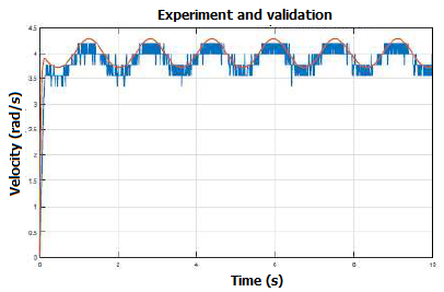
When implementing the controller in the microprocessor, a time of 13 seconds and a maximum position of 1.5708 rad were parameterized, equivalent to 90º in the trajectory movement, results that can be observed in Fig. 10. Parrafo X.
Fig. 10. Controller tracking result experiment
As it can be seen, the implemented control system meets the requirements of the trajectory tracking implemented during the test.
7. CONCLUSION
A mechatronic knee orthosis for rehabilitation is developed using a compliant mechanism, which results in a serial-elastic actuator. This allows attaching a patient’s lower limb to the orthosis to perform therapy with a self-adaptive alignment. The orthosis includes a gearmotor with a feedback controller that ensures a predefined motion pattern. This strategy allows physicians to track the evolution of the therapy and guarantees the reliability of the treatment. The orthosis is experimentally evaluated in a testbed that shows its robustness and performance. Thus, evidence shows potential for applications on post-surgical knee recovery treatments.REFERENCES
J. Vergara, M. Díaz, A. Ortega, J. Blanco, J. Hernández, and Herrera, 2004. “Protocolo de valoración de la patología de la rodilla,” Semergen, vol. 30, no. 5, pp. 178–87.L. Calderita, P. Bustos, C. S. Mejías, F. Fernández, R. Viciana, and A. Bandera, 2016. “Asistente robótico socialmente interactivo para terapias de rehabilitación motriz con pacientes de pediatría,” Revista Iberoamericana de Automática e Informática industrial, vol. 12, no. 1, pp. 99–110.
P. D. Neuhaus, J. H. Noorden, T. J. Craig, T. Torres, J. Kirschbaum, and J. E. Pratt, 2011. “Design and evaluation of mina: A robotic orthosis for paraplegics,” IEEE international conference on rehabilitation robotics. IEEE, 2011, pp. 1–8.
D. Ferris, G. Sawicki, and A. Domingo, “Powered lower limb orthoses for gait rehabilitation,” Topics in spinal cord injury rehabilitation, vol. 11, no. 2, pp. 34–49, 2005.
E. B. Castán, P. M. Ribas, M. V. Araiz, M. Aznar, R. V. Pascual, F. N. Teixido et al., 2012. “Dolor anterior de rodilla. una revisión en imágenes.” European Society of Radiology.
A. Espejo-Reina, M. Espejo Reina, G. García-Gutiérrez, J. Dalla Rosa Nogales, A. P. de la Blanca-Cobos, M. Prado, and A. E. Baena, 2018. “Lesiones de las raíces meniscales. estado actual,” Rev Esp Artrosc Cir Articul, vol. 25, no. Supl 1, pp. 29–45.
J. Raya Gonzalez, P. Gomez Piqueras, and J. Sanchez Sánchez, 2018. “Effect of an eccentric load resistance training program on the rehabilitation of medial collateral ligament injuries. a case study”, Retos nuevas tendencias en educación física deporte y recreación, no. 33, pp. 157—161.
W. M. Dos Santos, G. A. Caurin, and A. A. Siqueira, 2017. “Design and control of an active knee orthosis driven by a rotary series elastic actuator,” Control Engineering Practice, vol. 58, pp. 307–318.
N. Paine, S. Oh, and L. Sentis, 2013. “Design and control considerations for high-performance series elastic actuators,” IEEE/ASME Transactions on Mechatronics, vol. 19, no. 3, pp. 1080–1091.
W. J. Arcos-Legarda, 2013. “Control automático de un exoesqueleto de marcha para pacientes con discapacidad motora,” Tesis maestría, Universidad Nacional De Colombia.
C. Ortiz, F. Fernando et al., 2010. “Estudio de la resistencia de fatiga del acero sae 5160 antes y después de proceso shot peening,” B.S. thesis, Universidad Autónoma de Occidente.
S. Hernández, “Anatomía de la pierna humana,” catarina UDLAP.
F. Sergi, D. Accoto, G. Carpino, N. L. Tagliamonte, and E. Guglielmelli, 2012. “Design and characterization of a compact rotary series elastic actuator for knee assistance during overground walking,” 4th IEEE RAS & EMBS International Conference on Biomedical Robotics and Biomechatronics (BioRob). IEEE, 2012, pp. 1931– 1936.