Revista Colombiana de
Tecnologías de Avanzada
Tecnologías de Avanzada
Recibido: 14 de marzo de 2022
Aceptado: 26 de septiembre de 2022
Aceptado: 26 de septiembre de 2022
MATHEMATICAL MODEL FOR THE DETERMINATION OF VOLT-AMPERE CHARACTERISTICS IN SOLAR PHOTOCELLS
MODELO MATEMÁTICO PARA LA DETERMINACIÓN DE LAS CARACTERÍSTICAS VOLTIOAMPERIO EN FOTOCÉLULAS SOLARES
 MSc. Yadelvys García Figueredo*,
 PhD. Francisco García Reina*,
 PhD. Juan Antonio Martín Alfonso*.
*Universidad de Ciego de Ávila Máximo Gómez Báez (UNICA), Facultad de Informática y Ciencias Exactas y Facultad de Ciencias Técnicas, Departamento de Matemática y Física, Grupo de Investigación en Energía.
Carretera de Morón Km 9 ½, Ciego de Ávila, Cuba.
Tel.: 53-56711472, Ext. 1060, 53-54378566, Ext. 1060, 53-52149735, Ext. 1060
E-mail: {yadelvysgarciafigueredo, pancho30011918}@gmail.com, jamartin@unica.cu
MODELO MATEMÁTICO PARA LA DETERMINACIÓN DE LAS CARACTERÍSTICAS VOLTIOAMPERIO EN FOTOCÉLULAS SOLARES
 MSc. Yadelvys García Figueredo*,
 PhD. Francisco García Reina*,
 PhD. Juan Antonio Martín Alfonso*.
*Universidad de Ciego de Ávila Máximo Gómez Báez (UNICA), Facultad de Informática y Ciencias Exactas y Facultad de Ciencias Técnicas, Departamento de Matemática y Física, Grupo de Investigación en Energía.
Carretera de Morón Km 9 ½, Ciego de Ávila, Cuba.
Tel.: 53-56711472, Ext. 1060, 53-54378566, Ext. 1060, 53-52149735, Ext. 1060
E-mail: {yadelvysgarciafigueredo, pancho30011918}@gmail.com, jamartin@unica.cu
Cómo citar: García Figueredo, Y., García Reina, F., & Martín Alfonso, J. A. (2022). MODELO MATEMÁTICO PARA LA DETERMINACIÓN
DE LAS CARACTERÍSTICAS VOLTIOAMPERIO EN FOTOCÉLULAS SOLARES. REVISTA COLOMBIANA DE TECNOLOGIAS DE AVANZADA (RCTA), 2(40), 103-109.
https://doi.org/10.24054/rcta.v2i40.2358
Derechos de autor 2022 Revista Colombiana de Tecnologías de Avanzada (RCTA).
Esta obra está bajo una licencia internacional Creative Commons Atribución-NoComercial 4.0.

Esta obra está bajo una licencia internacional Creative Commons Atribución-NoComercial 4.0.

Abstract: To use photovoltaic systems, it is necessary to measure precisely the light output that affects each unit of
surface in the locations to be installed, which is essential to assess your energy efficiency. For this, these cells must be calibrated and
their volt-ampere characteristics (I-V) known. The error made in determining these characteristics was evaluated using a simplified
mathematical model and comparing the result of both models with the experimental result of 95 Si photocells from the Combined Electronic
Components of the Pinar del Río province; facilitating the necessary calculation in the use of said cells as solar radiation sensors. The
experimental points were extracted using the OriginPro 2017 program and processed with the Mathcad 15.0 program and the mathematical theory of
numerical methods. The quality of the adjustment is determined by comparing the statistical coefficients R2 corresponding to the complete and
simplified equation, for which it has been found so far that said coefficient R2 of the simplified equation is better than that given by the
equipment with which experimental values and results are determined as good as with the complete equation.
Keywords: Si photocell, I-V characteristic, mathematical model, numerical methods.
Resumen: Para utilizar sistemas fotovoltaicos es necesario medir con precisión el flujo luminoso que incide en cada unidad de superficie en los lugares a instalar, lo cual es fundamental para evaluar su eficiencia energética. Para ello, estas celdas deben estar calibradas y conocer sus características voltamperio (I-V). El error cometido en la determinación de estas características se evaluó utilizando un modelo matemático simplificado y comparando el resultado de ambos modelos con el resultado experimental de fotocélulas de 95 Si de Componentes Electrónicos Combinados de la provincia de Pinar del Río; facilitando el cálculo necesario en el uso de dichas celdas como sensores de radiación solar. Los puntos experimentales se extrajeron con el programa OriginPro 2017 y se procesaron con el programa Mathcad 15.0 y la teoría matemática de métodos numéricos. La calidad del ajuste se determina comparando los coeficientes estadísticos R2 correspondientes a la ecuación completa y simplificada, para lo cual se ha encontrado hasta ahora que dicho coeficiente R2 de la ecuación simplificada es mejor que el dado por el equipo con el que se obtienen valores experimentales y los resultados se determinan tan buenos como con la ecuación completa.
Palabras clave: fotocélula de Si, característica I-V, modelo matemático, métodos numéricos.
Solar energy, the emblem of renewable energies, has seen a progression in recent years due to improvements in technology, associated with cost reduction and mainly thanks to the interest shown by a large number of countries
To determine how much solar radiation affects 1 m2 of surface, equipment with very expensive and slow technologies is used, since it cannot be put into practice in real time (online), which represents a great difficulty for its use in the country; it is for this reason that calibrated solar cells are used instead. For these cells to function correctly it is necessary to determine their I-V characteristics; and the mathematical model of a photovoltaic solar cell has a complex transcendent equation, this makes it very difficult to evaluate the cells as solar radiation sensors. However, when making certain approximations to such an equation, a simpler one is reached that facilitates the calculation of the I-V characteristics, but as a problem, it is unknown how precise it is. Therefore, the objective of the present work is to simplify a mathematical model for the determination of the volt-ampere characteristics of solar photocells, which facilitates the calculation of efficiency, which is necessary in the use of said cells as solar radiation sensors.
\[ I = I_L - I_D \left[ e^{\frac{q(V + R_s I)}{mKT}} - 1 \right] - \frac{V + R_s I}{R_{sh}} \hspace{1cm} (1)\] Then, for a photovoltaic module or panel, the characteristic equation is: \[ I = I_L - I_D \left[ e^{\frac{V + R_s I}{a}} - 1 \right] - \frac{V + R_s I}{R_{sh}} \hspace{1cm} (2)\] Where [a=mKTNs/q], where m is the dimensionless recombination coefficient of the cell (between 1 and 3); K is Boltzmann's constant (1.38∙10-23 J/K); q is the charge of the electron (1.6∙10-19 C); T is the temperature in Kelvin and Ns is the number of cells in the module.
\(I_L \approx I_{sc} \) , where \(I_L\) is the maximum intensity and \(I_{sc}\) is the short circuit intensity. \(I_D = I_L \cdot e^{\frac{V_{oc}}{a}} \) , where Voc is the open circuit voltage: \[ V_{oc} = \frac{mKT}{q} \ln \left( \frac{I_L}{I_D} \right) = mV_T \ln \left( \frac{I_L}{I_D} \right) \hspace{1cm}(3)\] \[ V_T = \frac{KT}{q} \hspace{1cm}(4)\]The series resistance is: \[ R_s = \frac{a \cdot \ln \left( 1 - \frac{I_{mp}}{I_L} \right) - V_{mp} + V_{oc}}{I_{mp}} \hspace{1cm}(5)\] Where \(I_{mp}\) and \(V_{mp}\) are the Intensity and Voltage at the point of maximum power given by the expressions: \[ I_{mp} = I_L \left( 1 - c^{-d} \right) \hspace{1cm}(6)\] \[ V_{mp} \approx V_{oc} \left( 1 - \frac{\ln c}{c} \right) \hspace{1cm}(7)\] Where: \[ c = 1 + \ln \left( \frac{I_L}{I_D} \right) \hspace{1cm} and \hspace{1cm} d = \frac{c}{c+1}\hspace{1cm}(8)\] Equation (2) is a transcendent equation, which makes the process cumbersome to determine the intensity I for the different voltage values V necessary for the evaluation of photovoltaic cells as sensors of solar radiation. To facilitate these calculations, a simpler equation can be arrived at by making an approximation, since the value of Rsh, the parallel resistance, which is found in the denominator of the term corresponding to the intensity of the current Ish, is much greater than its numerator and can be considered negligible. The characteristic equation for a PV module or panel is: \[ I = I_L - I_D \left[ e^{\frac{V + R_s I}{a}} - 1 \right] \hspace{1cm}(9)\] This equation defines I as an implicit function of V, but also defines V as an explicit function of I, obtaining the following expression. \[ V(I) = a \ln \left( \frac{I_D - I + I_L}{I_D} \right) - I R_s \hspace{1cm}(10)\]

Once these are obtained, they are introduced in the MathCad 15.0 program, which is a software designed mainly for the verification, validation, documentation and use of engineering calculations that allows exploring problems, formulating ideas, analyzing data, modeling and checking scenarios, determine the best solution; as figure 3 shows.
Note. a Fill Factor, area of the cell that is "filled" with solar radiation and converts it into electricity. b Efficiency. c Electro-optical parameters with their mean values and absolute errors of measurements from the root mean square deviation.
Below are scatter diagrams for the main electro-optical parameters of the 95 photovoltaic solar cells studied with their mean values and their respective maximum and minimum errors.
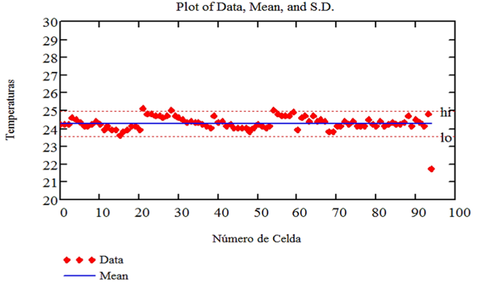
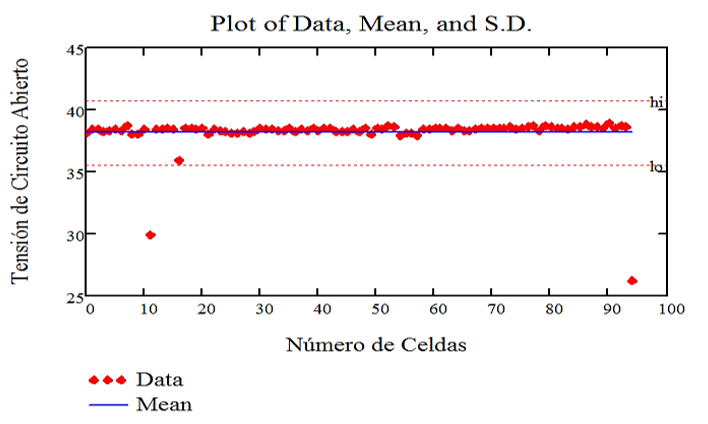
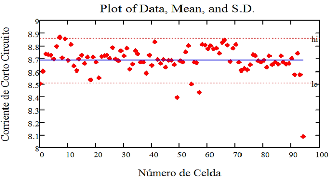
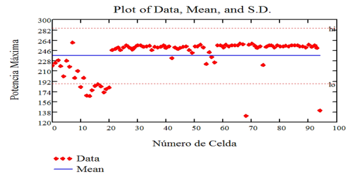
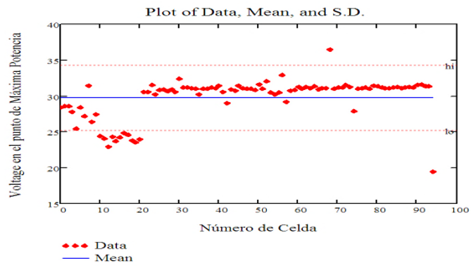
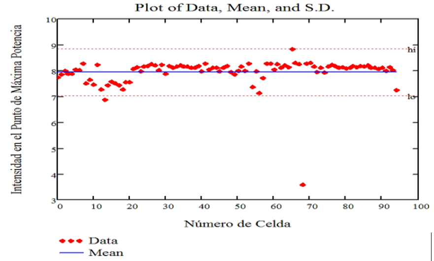
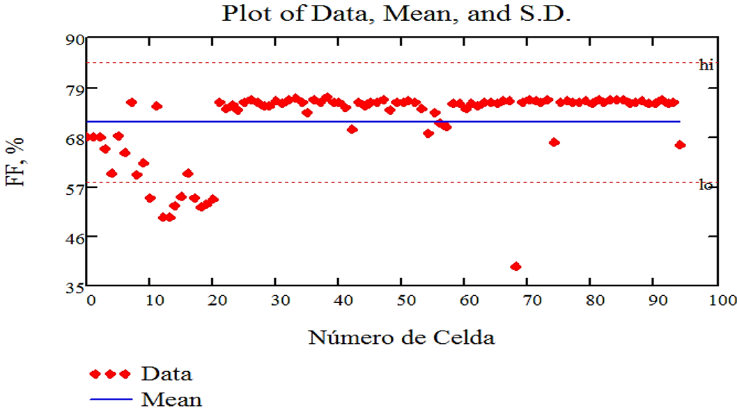
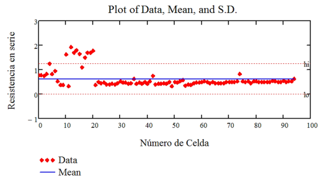
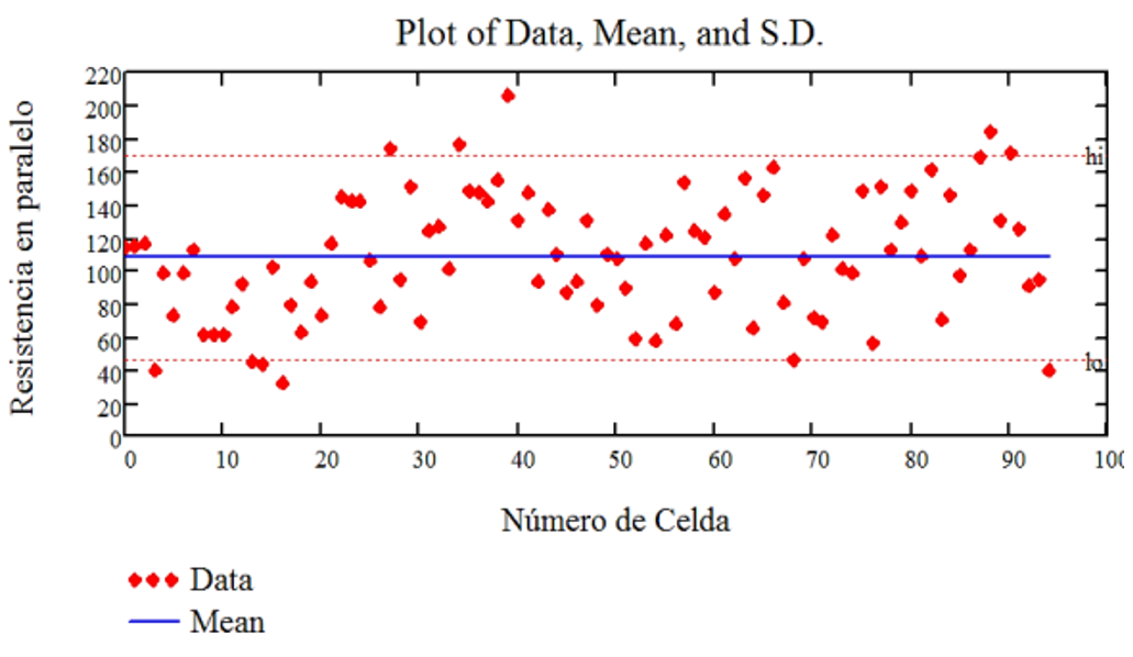
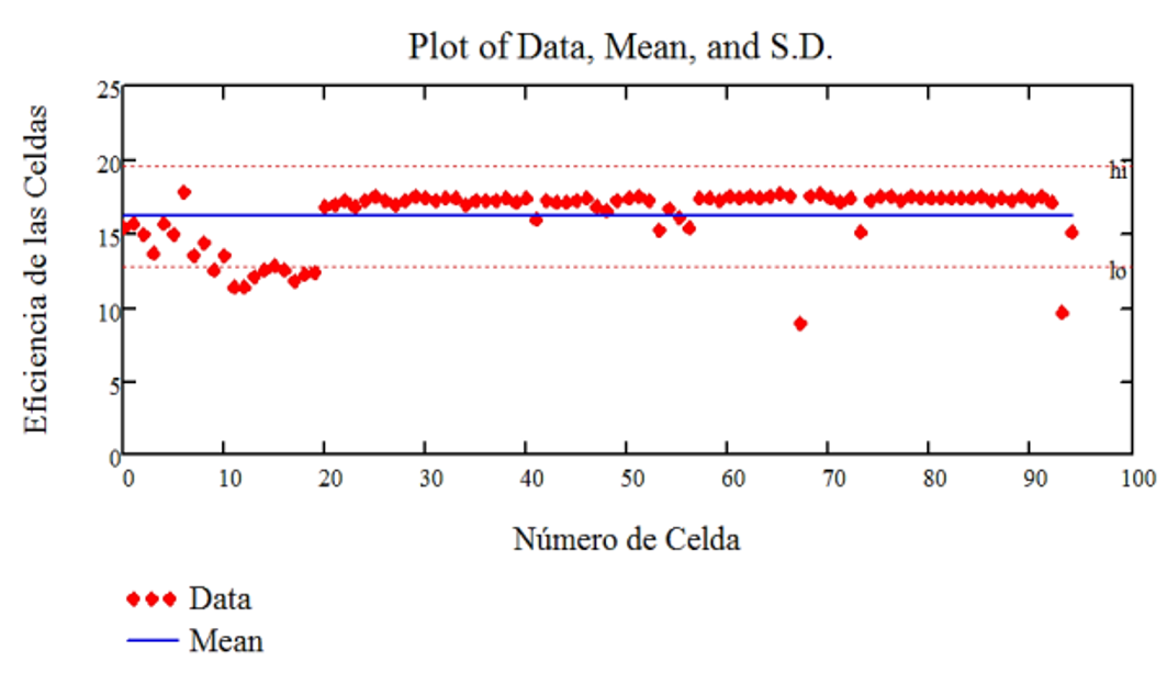
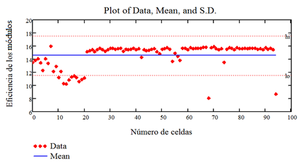
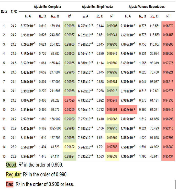
Figure 17 shows examples that are considered good, regular and bad, taking into account the quality of their adjustments according to R2 ; both for the exact model (complete equation) and for the approximate model (simplified equation) and for experimental values reported consecutively.
It can be concluded whether a batch is good, fair or bad depending on the percentage of cells classified as good, fair and bad. It can also be seen that the coefficient R2 of the simplified equation is better than the one given by the equipment with which the experimental values are determined and in the order of the R2 for the complex equation. That is to say, the results are as good as with the complete equation; in addition, the simplified equation is easier to work with, since it is possible to clear one variable as a function of another.
The results of the mathematical models were compared, both with the transcendental equation and with the simplified equation, with the experimental values; the simplified model has turned out to be a good one.
The approximate model was used without making large errors.
The quality of the solar cells for their use or not in the solar panels was determined from the electro-optical parameters given by the manufacturer.
Almanza Fundora, I. (2015). Desarrollo de un sistema para la medición de la eficiencia energética de celdas solares [Tesis de Maestría, Universidad de Ciego de Ávila Máximo Gómez Báez]. Ciego de Ávila: UNICA.
Alonso Montes, J. I., Fernández Durán, A., Jiménez Suárez, C., Lecuona Ribot, A., Mellado García, F., Plaza Fernández, J. F., Ramos González, V. y Sala Pano, G. (2002). Energía Solar Fotovoltaica. Colegio Oficial de Ingenieros de Telecomunicación. Madrid.
Bacus Charles, E. (2001). Solar Cells. IEEE Press, NY, USA.
Beltran Pérez, Y. (201). Evaluación del Sistema de Bombeo Solar Fotovoltaico para el Riego del Frijol en la UBPC Delia del Municipio Primero de Enero [Tesis de Maestría, Universidad de Ciego de Ávila Máximo Gómez Báez].
Berri, L. (2014). La energía solar en Cuba. Energía y tú, 12(2), 34-45.
Díaz González, C. A. (2018). Desarrollo de un sistema de medición de la irradiancia solar y su uso en el aprovechamiento de esta energía renovable [Tesis de Maestría, Universidad de Ciego de Ávila Máximo Gómez Báez].
Duffie, J. A. y Beckman, W. A. (2013). Solar Engineering of Thermal Processes. Publicado por John Wiley & Sons, Inc., Hoboken, Nueva Jersey.
García López, L. (2018). Determinación de la eficiencia de conversión de corriente directa en corriente alterna en los sistemas fotovoltaicos instalados en la provincia [Tesis de Maestría, Universidad de Ciego de Ávila Máximo Gómez Báez].
Green, M. A. (2015). Solar Cell Operating principles, technology, and system aplications. Prentice-Hall.
Gudiño Ayala, D. (2014). Calibración de Piranómetros [Reporte de Proyecto No. 22, Unidad Académica de Tecnología Intermedia, ITESO].
Hermosillo, J. J. (2012). Destilación Solar. Cuaderno Huella No. 16, ITESO México.
Iqbal, M. (1983). An introduction to Solar Radiation. Toronto: Academic Press.
Janes, J. Flujo Luminoso, Cap. III. Mediciones de la luz. Madrid : Revesté.
Kapoor K. (2017). Evolution of solar energy in India: A review. Renewable and Sustainable Energy Reviews, 40, 475–487.
Mazón Hernandez, R. (2014). Estudio de la influencia de la rerigeración con aire de forma natural e inducida en el comportamiento de instalaciones fotovoltaicas. Cartagena.
Meinel A. y Meinel B. (2013). Solar Energy. Addison Wesley. NY, USA.
Monera Olmos, F. (2015). Breve historia de la Energía Solar Fotovoltaica. Madrid.
Morales A. (2014). Diseño optimo y realización de celdas solares de silicio para producción industrial. Revista Mexicana de Física, 49 (4), 35.
Nelson J. (2006). The Physics of Solar Cells. Imperial College Press, London, UK.
Opálková M. (2018). A Database of 10 min Average Measurements of Solar Radiation and Meteorological Variables in Ostrava, Czech Republic. Earth Syst. Sci., 5, 345-356.
Osinergmin. (2013). Introducción a las Energías Renovables. San Borja, Perú.
Oyarce, Andrés. (2010). Guía del Usuario Xbee Pro S1. Santiago, Chile : s.n.
PCC. (2009). Lineamientos de la política económica y social del partido y la revolución.
Roldan, J. (2008). Fuentes de Energía. Paraninfo.
Sarmiento Sera, A. (2013). Energía Solar Fotovoltaica. Temas Seleccionados. La Habana: Editorial Acadamia.
Sears, F. W., Zemansky, M. W., Young, H. D. y Freedman, R. A. (2013). Física Universitaria con Física Moderna. Ed. 13, Vol. 2, Naucalpan de Juárez, México, México: PEARSON.
Segura, R. B. (2002). Del desarrollo sostenible según Brundtland a la sostenibilidad como biomimesis. Bilbao: Creative Commons.
Sevil, R. M. (2006). Proyecto de aprovechamiento de la energía solar para la producción de electricidad en el nuevo edificio de la E.T.S.E. Tarragona. Tarragona.
Ulloa Turjillo, L. (2016). Ciego de Ávila por un mayor uso de energía renovable. ACN.
UNE. (2018). Programa de desarrollo de la provincia de Ciego de Ávila. Ciego de Ávila.
Willians Fonseca, R. M. (2012). Análisis del Comportamiento de Módulos Fotovoltaicos. Diagnóstico, Modelado Matemático de curvas I-V y P-V, y construcción de Prototipo de Trazador de Curvas I-V. Braganca: IPB-ESTIG.
Wolfgang Boer, K. (2002). Survey of Semiconductor Physics. s.1.: Springer.
Cata Sánchez, J. E. y Rodríguez Sócola, F. M. (2015). Análisis Matemático de un Panel Solar Fotovoltaico de Silicio [Tesis de Grado, Universidad Politécnica Salesiana, Guayaquil]. https://dspace.ups.edu.ec/bitstream/123456789/10250/1/UPS-GT001338.pdf
Chávez Guerrero, M. A. (2012). Proyecto de factivilidad para uso de paneles solares en generación fotovoltaica de electricidad en un complejo habitacional San Antonio de Riobamba [Tesis de Grado, Escuela Superior Politécnica de Chimborazo]. http://dspace.espoch.edu.ec/handle/123456789/2478
De Vos, A. y Pauwels, H. (1981). On the thermodynamics limit of photovoltaic energy. Applied Physics, 25(2), 119-125. https://link.springer.com/journal/339/volumes-and-issues/25-2
Ekici C. (2017). Total Global Solar Radiation Estimation with Relative Humidity and Air Temperature Extremes in Ireland and Holland. Geosci. Instrum. Method. Data Syst. 12, 78-90. https://gi.copernicus.org/preprints/gi-2017-52/gi-2017-52.pdf
Ginley, D., Green, M. A. y Collins, R. (2008). Solar Energy Conversion Toward 1 Terawatt, MRS Bulletin, 33 (4), 355. https://doi.org/10.1557/mrs2008.71
SOPELIA. (2016). Solar Platform America Latina. Obtenido de http://www.energiasolar.lat/cuba-solar-pv/
Keywords: Si photocell, I-V characteristic, mathematical model, numerical methods.
Resumen: Para utilizar sistemas fotovoltaicos es necesario medir con precisión el flujo luminoso que incide en cada unidad de superficie en los lugares a instalar, lo cual es fundamental para evaluar su eficiencia energética. Para ello, estas celdas deben estar calibradas y conocer sus características voltamperio (I-V). El error cometido en la determinación de estas características se evaluó utilizando un modelo matemático simplificado y comparando el resultado de ambos modelos con el resultado experimental de fotocélulas de 95 Si de Componentes Electrónicos Combinados de la provincia de Pinar del Río; facilitando el cálculo necesario en el uso de dichas celdas como sensores de radiación solar. Los puntos experimentales se extrajeron con el programa OriginPro 2017 y se procesaron con el programa Mathcad 15.0 y la teoría matemática de métodos numéricos. La calidad del ajuste se determina comparando los coeficientes estadísticos R2 correspondientes a la ecuación completa y simplificada, para lo cual se ha encontrado hasta ahora que dicho coeficiente R2 de la ecuación simplificada es mejor que el dado por el equipo con el que se obtienen valores experimentales y los resultados se determinan tan buenos como con la ecuación completa.
Palabras clave: fotocélula de Si, característica I-V, modelo matemático, métodos numéricos.
1. INTRODUCTION
Fossil fuels are finite resources that will inexorably run out
(Díaz, 2018)
. The current energy system is based on these sources that lead to a series of environmental and sustainability problems, among which we can
mention the greenhouse effect
Desarrollo de un sistema de medición de la irradiancia solar y su uso en el aprovechamiento de esta energía renovable [Tesis de Maestría,
Universidad de Ciego de Ávila Máximo Gómez Báez].
(García, 2018)
. Fortunately, there are also renewable energies; within this group we find wind energy, photovoltaic solar energy, thermal solar energy,
hydraulic energy, energy from biomass and organic waste
Determinación de la eficiencia de conversión de corriente directa en corriente alterna en los sistemas fotovoltaicos instalados en la
provincia [Tesis de Maestría, Universidad de Ciego de Ávila Máximo Gómez Báez].
(Beltran, 2015)
.
Evaluación del Sistema de Bombeo Solar Fotovoltaico para el Riego del Frijol en la UBPC Delia del Municipio Primero de Enero [Tesis de
Maestría, Universidad de Ciego de Ávila Máximo Gómez Báez].
Solar energy, the emblem of renewable energies, has seen a progression in recent years due to improvements in technology, associated with cost reduction and mainly thanks to the interest shown by a large number of countries
(Berri, 2014
;
La energía solar en Cuba. Energía y tú, 12(2), 34-45.
Opálková, 2018)
. In photovoltaic systems it is essential to measure the efficiency of the solar cells, since this allows knowing how much power of solar
radiation (W/m2) each one absorbs, for which it is also necessary to know precisely how much solar energy reaches each location per area unit
in one second. Then, the amount of solar energy and its conversion efficiency into electrical energy are the two fundamental parameters to be
measured and controlled in any photovoltaic system that uses solar energy
A Database of 10 min Average Measurements of Solar Radiation and Meteorological Variables in Ostrava, Czech Republic. Earth Syst. Sci., 5,
345-356.
(Alan et al., 1998)
. This efficiency is the ratio between the number of electrons released for electrical conduction and the number of light photons reaching the
cell, called the internal quantum efficiency
Physic in science and industry. New York, U.S.A: McGraw-Hill.
(Janes, 2012
;
Flujo Luminoso, Cap. III. Mediciones de la luz. Madrid: Revesté.
Wolfgang Boer, 2002)
. Survey of Semiconductor Physics. s.1.: Springer.
To determine how much solar radiation affects 1 m2 of surface, equipment with very expensive and slow technologies is used, since it cannot be put into practice in real time (online), which represents a great difficulty for its use in the country; it is for this reason that calibrated solar cells are used instead. For these cells to function correctly it is necessary to determine their I-V characteristics; and the mathematical model of a photovoltaic solar cell has a complex transcendent equation, this makes it very difficult to evaluate the cells as solar radiation sensors. However, when making certain approximations to such an equation, a simpler one is reached that facilitates the calculation of the I-V characteristics, but as a problem, it is unknown how precise it is. Therefore, the objective of the present work is to simplify a mathematical model for the determination of the volt-ampere characteristics of solar photocells, which facilitates the calculation of efficiency, which is necessary in the use of said cells as solar radiation sensors.
2. MATERIALS AND METHODS
2.1 Theoretical Foundation
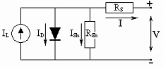
The PV solar cell can be modeled by means of the equivalent circuit shown in figure 1, using the laws of circuit theory, the following mathematical model for the solar cell is obtained
(Morales, 2014)
.
Diseño óptimo y realización de celdas solares de silicio para producción industrial. Revista Mexicana de Física, 49(4), 35.
\[ I = I_L - I_D \left[ e^{\frac{q(V + R_s I)}{mKT}} - 1 \right] - \frac{V + R_s I}{R_{sh}} \hspace{1cm} (1)\] Then, for a photovoltaic module or panel, the characteristic equation is: \[ I = I_L - I_D \left[ e^{\frac{V + R_s I}{a}} - 1 \right] - \frac{V + R_s I}{R_{sh}} \hspace{1cm} (2)\] Where [a=mKTNs/q], where m is the dimensionless recombination coefficient of the cell (between 1 and 3); K is Boltzmann's constant (1.38∙10-23 J/K); q is the charge of the electron (1.6∙10-19 C); T is the temperature in Kelvin and Ns is the number of cells in the module.

Fig. 1 Equivalent Circuit of a Photovoltaic Solar Cell, by Díaz, 2018
\(I_L \approx I_{sc} \) , where \(I_L\) is the maximum intensity and \(I_{sc}\) is the short circuit intensity. \(I_D = I_L \cdot e^{\frac{V_{oc}}{a}} \) , where Voc is the open circuit voltage: \[ V_{oc} = \frac{mKT}{q} \ln \left( \frac{I_L}{I_D} \right) = mV_T \ln \left( \frac{I_L}{I_D} \right) \hspace{1cm}(3)\] \[ V_T = \frac{KT}{q} \hspace{1cm}(4)\]The series resistance is: \[ R_s = \frac{a \cdot \ln \left( 1 - \frac{I_{mp}}{I_L} \right) - V_{mp} + V_{oc}}{I_{mp}} \hspace{1cm}(5)\] Where \(I_{mp}\) and \(V_{mp}\) are the Intensity and Voltage at the point of maximum power given by the expressions: \[ I_{mp} = I_L \left( 1 - c^{-d} \right) \hspace{1cm}(6)\] \[ V_{mp} \approx V_{oc} \left( 1 - \frac{\ln c}{c} \right) \hspace{1cm}(7)\] Where: \[ c = 1 + \ln \left( \frac{I_L}{I_D} \right) \hspace{1cm} and \hspace{1cm} d = \frac{c}{c+1}\hspace{1cm}(8)\] Equation (2) is a transcendent equation, which makes the process cumbersome to determine the intensity I for the different voltage values V necessary for the evaluation of photovoltaic cells as sensors of solar radiation. To facilitate these calculations, a simpler equation can be arrived at by making an approximation, since the value of Rsh, the parallel resistance, which is found in the denominator of the term corresponding to the intensity of the current Ish, is much greater than its numerator and can be considered negligible. The characteristic equation for a PV module or panel is: \[ I = I_L - I_D \left[ e^{\frac{V + R_s I}{a}} - 1 \right] \hspace{1cm}(9)\] This equation defines I as an implicit function of V, but also defines V as an explicit function of I, obtaining the following expression. \[ V(I) = a \ln \left( \frac{I_D - I + I_L}{I_D} \right) - I R_s \hspace{1cm}(10)\]
2.2 Materials, Equipment and Methods to Follow
95 images of 95 graphs of the I-V characteristics corresponding to 95 photocells are taken as a sample. These data were supplied by the UEB for PV energy, CCE Combined for Electronic Components, located on Álvaro Barba Airport Highway Km 2 ½, Colon Avenue, Passage A, No.16 between Álvaro Barba and Passage B, Pinar del Río province, Cuba. In the conformation of the solar panels, technology from the firm EPSON or Seiko Epson Corporation is used, which is a Japanese company and one of the world's largest manufacturers of electronic components such as SCARA robots for industrial use. While the Solar Simulator HSM2 is used to test the main electro-optical characteristics of solar cells and map the I-V curve. The 95 images are digitized with the OriginPro 2017 program to extract the experimental points corresponding to the characteristic curves of intensity I versus voltage V. The program is data analysis and graph generation software. It is a leader in the scientific-technical sector; belongs to OroginLab Corporation and is used to import, graph, explore, analyze and interpret data as needed.
Fig. 2 Photo Taken at OriginPro 2017 Program
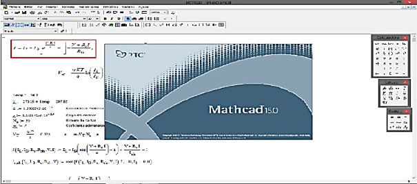
Once these are obtained, they are introduced in the MathCad 15.0 program, which is a software designed mainly for the verification, validation, documentation and use of engineering calculations that allows exploring problems, formulating ideas, analyzing data, modeling and checking scenarios, determine the best solution; as figure 3 shows.

Fig. 3 Photo Taken from the MathCad 15.0 Program
3. PRESENTATION AND DISCUSSION OF THE RESULTS
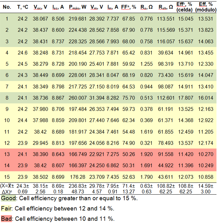
The 95 images were digitized where the corresponding data to be processed in the MathCad program were obtained, which consist of its main electro-optical parameters. Taking into account their efficiency values, they are classified by colors according to the order of quality, very good (High quality), fair (Medium quality) and poor (Low quality), as shown in the table in figure 4.
Fig. 4 Sample of 15 of the 95 Photocells with their Main Electro-Optic Parameters classified by Colors into Good, Regular and Bad according
to their Efficiency
Note. a Fill Factor, area of the cell that is "filled" with solar radiation and converts it into electricity. b Efficiency. c Electro-optical parameters with their mean values and absolute errors of measurements from the root mean square deviation.
Below are scatter diagrams for the main electro-optical parameters of the 95 photovoltaic solar cells studied with their mean values and their respective maximum and minimum errors.

Fig. 5 Graphic Representation of the Temperature Measurements, with their Respective Average Value and Errors

Fig. 6 Graphic Representation of the Open Circuit Voltage Measurements with their Respective Average Value and Errors

Fig. 7 Graphic Representation of the Short Circuit Current Measurements with their Respective Average Value and Errors

Fig. 8 Graphic Representation of the Maximum Power Measurements with their Respective Average Value and Errors

Fig. 9 Graphic Representation of the Measurements of the Voltage at the Point of Maximum Power with its Respective Mean Value and Errors

Fig. 10 Graphic Representation of the Measurements of the Intensity at the Point of Maximum Power with its Respective Average Value and
Errors

Fig. 11 Graphic Representation of the Filling Factor Measurements with their Respective Mean Value and Errors

Fig. 12 Graphic Representation of the Resistance Measurements in Series with their Respective Average Value and Errors

Fig. 13 Graphic Representation of Resistance Measurements in Parallel with their Respective Mean Value and Errors

Fig. 14 Graphic Representation of the Efficiency of the Cells, in %, with their Respective Average Value and Errors

Fig. 15 Graphic Representation of the Efficiency of the Modules, in %, with their Respective Average Value and Errors
3.1 Adjustments of the Experimental Results to the Exact and Approximate Models
The table in figure 16 shows 15 examples of the adjustments with the main electro-optical parameters of the 95 cells studied for the exact model, for the approximate model and for reported experimental values. The table in figure 16 shows 15 examples of the adjustments with the main electro-optical parameters of the 95 cells studied for the exact model, for the approximate model and for reported experimental values. The quality of the fits is determined by comparing the corresponding statistical coefficients of determination R2 (error), where the perfect fit corresponds to R2=1.
Fig. 16 Sample of 15 of the 95 Fits for the Exact Model, the Approximate Model and for the Reported Experimental Values
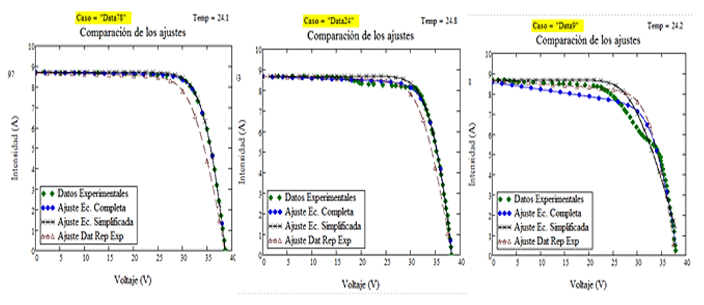
Figure 17 shows examples that are considered good, regular and bad, taking into account the quality of their adjustments according to R2 ; both for the exact model (complete equation) and for the approximate model (simplified equation) and for experimental values reported consecutively.

Fig. 17 Examples of Adjustments Classified as Good, Regular and Bad according to their R2
3.2 Analysis and Comparison
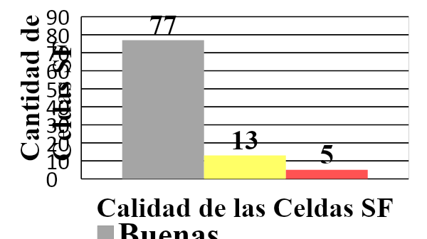
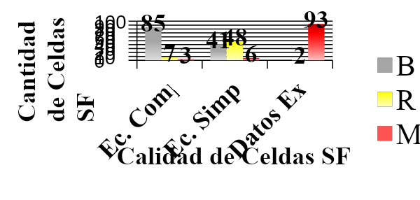
The quality of solar cells for use or not in solar panels is determined from the electro-optical parameters given by the manufacturer, and also the number of cells that are classified as good, fair and poor in quality, according to the quality of the corresponding adjustments from the R2 of each one with the main electro-optical parameters.
Fig. 18 Quality of the SF Cells Classified as Good, Regular and Bad According to their Efficiency

Fig. 19 Quality of the SF Cells According to the Quality of Fit R2 for the Exact, Approximate Models and for Reported Experimental Points
It can be concluded whether a batch is good, fair or bad depending on the percentage of cells classified as good, fair and bad. It can also be seen that the coefficient R2 of the simplified equation is better than the one given by the equipment with which the experimental values are determined and in the order of the R2 for the complex equation. That is to say, the results are as good as with the complete equation; in addition, the simplified equation is easier to work with, since it is possible to clear one variable as a function of another.
4. CONCLUSIONS
Experimental data were extracted from their corresponding I-V curve images of the 95 photocells.The results of the mathematical models were compared, both with the transcendental equation and with the simplified equation, with the experimental values; the simplified model has turned out to be a good one.
The approximate model was used without making large errors.
The quality of the solar cells for their use or not in the solar panels was determined from the electro-optical parameters given by the manufacturer.
5. REFERENCES
Alan, H., Cromer, y Fernández Ferrer, J. (1998). Physic in science and industry. New York, U.S.A: McGraw-Hill.Almanza Fundora, I. (2015). Desarrollo de un sistema para la medición de la eficiencia energética de celdas solares [Tesis de Maestría, Universidad de Ciego de Ávila Máximo Gómez Báez]. Ciego de Ávila: UNICA.
Alonso Montes, J. I., Fernández Durán, A., Jiménez Suárez, C., Lecuona Ribot, A., Mellado García, F., Plaza Fernández, J. F., Ramos González, V. y Sala Pano, G. (2002). Energía Solar Fotovoltaica. Colegio Oficial de Ingenieros de Telecomunicación. Madrid.
Bacus Charles, E. (2001). Solar Cells. IEEE Press, NY, USA.
Beltran Pérez, Y. (201). Evaluación del Sistema de Bombeo Solar Fotovoltaico para el Riego del Frijol en la UBPC Delia del Municipio Primero de Enero [Tesis de Maestría, Universidad de Ciego de Ávila Máximo Gómez Báez].
Berri, L. (2014). La energía solar en Cuba. Energía y tú, 12(2), 34-45.
Díaz González, C. A. (2018). Desarrollo de un sistema de medición de la irradiancia solar y su uso en el aprovechamiento de esta energía renovable [Tesis de Maestría, Universidad de Ciego de Ávila Máximo Gómez Báez].
Duffie, J. A. y Beckman, W. A. (2013). Solar Engineering of Thermal Processes. Publicado por John Wiley & Sons, Inc., Hoboken, Nueva Jersey.
García López, L. (2018). Determinación de la eficiencia de conversión de corriente directa en corriente alterna en los sistemas fotovoltaicos instalados en la provincia [Tesis de Maestría, Universidad de Ciego de Ávila Máximo Gómez Báez].
Green, M. A. (2015). Solar Cell Operating principles, technology, and system aplications. Prentice-Hall.
Gudiño Ayala, D. (2014). Calibración de Piranómetros [Reporte de Proyecto No. 22, Unidad Académica de Tecnología Intermedia, ITESO].
Hermosillo, J. J. (2012). Destilación Solar. Cuaderno Huella No. 16, ITESO México.
Iqbal, M. (1983). An introduction to Solar Radiation. Toronto: Academic Press.
Janes, J. Flujo Luminoso, Cap. III. Mediciones de la luz. Madrid : Revesté.
Kapoor K. (2017). Evolution of solar energy in India: A review. Renewable and Sustainable Energy Reviews, 40, 475–487.
Mazón Hernandez, R. (2014). Estudio de la influencia de la rerigeración con aire de forma natural e inducida en el comportamiento de instalaciones fotovoltaicas. Cartagena.
Meinel A. y Meinel B. (2013). Solar Energy. Addison Wesley. NY, USA.
Monera Olmos, F. (2015). Breve historia de la Energía Solar Fotovoltaica. Madrid.
Morales A. (2014). Diseño optimo y realización de celdas solares de silicio para producción industrial. Revista Mexicana de Física, 49 (4), 35.
Nelson J. (2006). The Physics of Solar Cells. Imperial College Press, London, UK.
Opálková M. (2018). A Database of 10 min Average Measurements of Solar Radiation and Meteorological Variables in Ostrava, Czech Republic. Earth Syst. Sci., 5, 345-356.
Osinergmin. (2013). Introducción a las Energías Renovables. San Borja, Perú.
Oyarce, Andrés. (2010). Guía del Usuario Xbee Pro S1. Santiago, Chile : s.n.
PCC. (2009). Lineamientos de la política económica y social del partido y la revolución.
Roldan, J. (2008). Fuentes de Energía. Paraninfo.
Sarmiento Sera, A. (2013). Energía Solar Fotovoltaica. Temas Seleccionados. La Habana: Editorial Acadamia.
Sears, F. W., Zemansky, M. W., Young, H. D. y Freedman, R. A. (2013). Física Universitaria con Física Moderna. Ed. 13, Vol. 2, Naucalpan de Juárez, México, México: PEARSON.
Segura, R. B. (2002). Del desarrollo sostenible según Brundtland a la sostenibilidad como biomimesis. Bilbao: Creative Commons.
Sevil, R. M. (2006). Proyecto de aprovechamiento de la energía solar para la producción de electricidad en el nuevo edificio de la E.T.S.E. Tarragona. Tarragona.
Ulloa Turjillo, L. (2016). Ciego de Ávila por un mayor uso de energía renovable. ACN.
UNE. (2018). Programa de desarrollo de la provincia de Ciego de Ávila. Ciego de Ávila.
Willians Fonseca, R. M. (2012). Análisis del Comportamiento de Módulos Fotovoltaicos. Diagnóstico, Modelado Matemático de curvas I-V y P-V, y construcción de Prototipo de Trazador de Curvas I-V. Braganca: IPB-ESTIG.
Wolfgang Boer, K. (2002). Survey of Semiconductor Physics. s.1.: Springer.
WEB SITES
Al-Taani, H. y Arabasi, S. (2018). Solar Irradiance Measurements Using Smart Devices: A Cost-Effective Technique for Estimation of Solar Irradiance for Sustainable Energy Systems. Sustainability, 10(2), 508-515. https://doi.org/10.3390/su10020508Cata Sánchez, J. E. y Rodríguez Sócola, F. M. (2015). Análisis Matemático de un Panel Solar Fotovoltaico de Silicio [Tesis de Grado, Universidad Politécnica Salesiana, Guayaquil]. https://dspace.ups.edu.ec/bitstream/123456789/10250/1/UPS-GT001338.pdf
Chávez Guerrero, M. A. (2012). Proyecto de factivilidad para uso de paneles solares en generación fotovoltaica de electricidad en un complejo habitacional San Antonio de Riobamba [Tesis de Grado, Escuela Superior Politécnica de Chimborazo]. http://dspace.espoch.edu.ec/handle/123456789/2478
De Vos, A. y Pauwels, H. (1981). On the thermodynamics limit of photovoltaic energy. Applied Physics, 25(2), 119-125. https://link.springer.com/journal/339/volumes-and-issues/25-2
Ekici C. (2017). Total Global Solar Radiation Estimation with Relative Humidity and Air Temperature Extremes in Ireland and Holland. Geosci. Instrum. Method. Data Syst. 12, 78-90. https://gi.copernicus.org/preprints/gi-2017-52/gi-2017-52.pdf
Ginley, D., Green, M. A. y Collins, R. (2008). Solar Energy Conversion Toward 1 Terawatt, MRS Bulletin, 33 (4), 355. https://doi.org/10.1557/mrs2008.71
SOPELIA. (2016). Solar Platform America Latina. Obtenido de http://www.energiasolar.lat/cuba-solar-pv/